EE案例 | Filter Design 这是一个电路设计的project 包含了已经完成的report和仿真模拟的答案。
UNIVERSITY OF TASMANIA SCHOOL ENGINEERING
KNE488 RF project (12.5%) Due in Week 13
Filter Design
Design/Derive (determine the element values) for a N = 2 element equal-ripple filter if the ripple specification is 1.0dB. Do not use tables! Start with the definition of the power loss ratio. Prototype values only are
T N (w) for N=2 is T 2 (w) = (2w2-1).
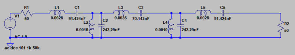
Determine the values of the reactive components (inductances and capacitances) for a 5th order 3dB bandpass Chebycheff filter with load and source impedances of 50W. The bandwidth is to be 4kHz, in this case, between 8kHz and
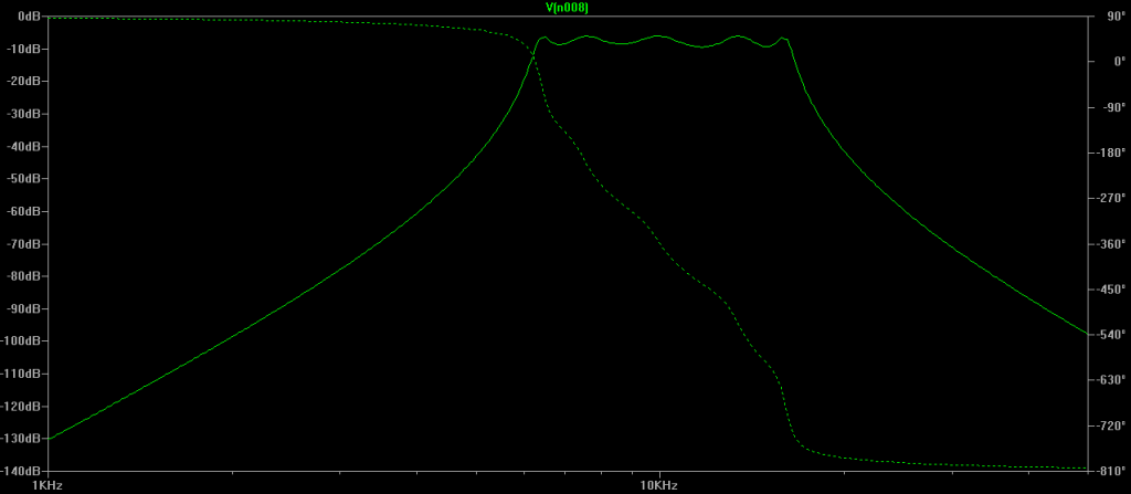
Plot the frequency response (amplitude and phase) of question
Determine the values of the reactive components (inductances and capacitances) for a 5th order low-pass-prototype with source and load terminations of 1 ohm for the following 3cases:
Butterworth
Chebycheff 3dB
Bessel
Plot the frequency response of the 3 filters of Question 4 on a suitable frequency scale and compare and briefly discuss the different frequency
In the discussion, you may consider the following points:
The Bessel filter values decrease monotonically,why?
Compare the cutoff rates, phase responses and pass band attenuations between the
To compare the filters, you should normalize the attenuation magnitude to zero dB. State how this is done in the simulation and ensure that this is done for any comparison
SPICE is a suitable tool for simulating the various filters.
END
成果展示图:
EE案例 | Filter Design
EE案例 | Filter Design